WELCOME TO THE MELTON & DISTRICT MODEL CLUB WEBSITE
During the Autumn & Winter season, our Clubhouse will be open from 8pm on Wednesday Evenings.
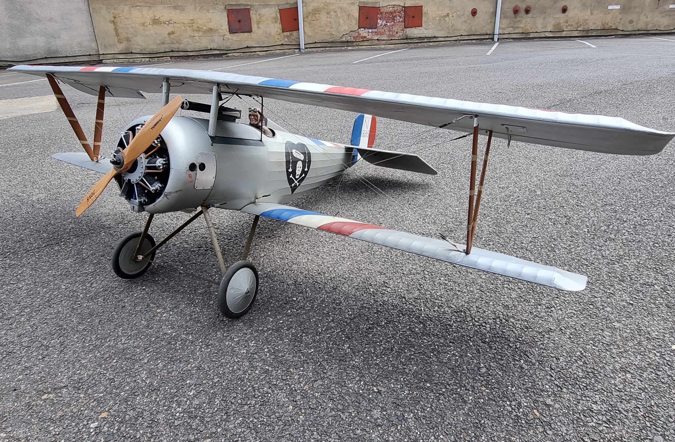
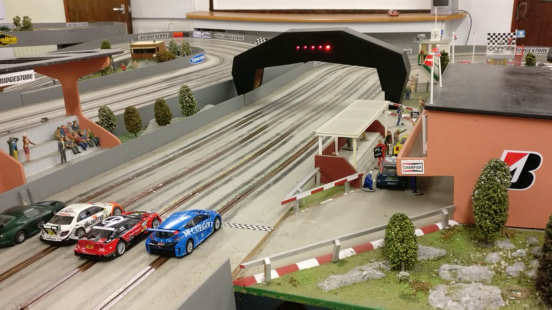
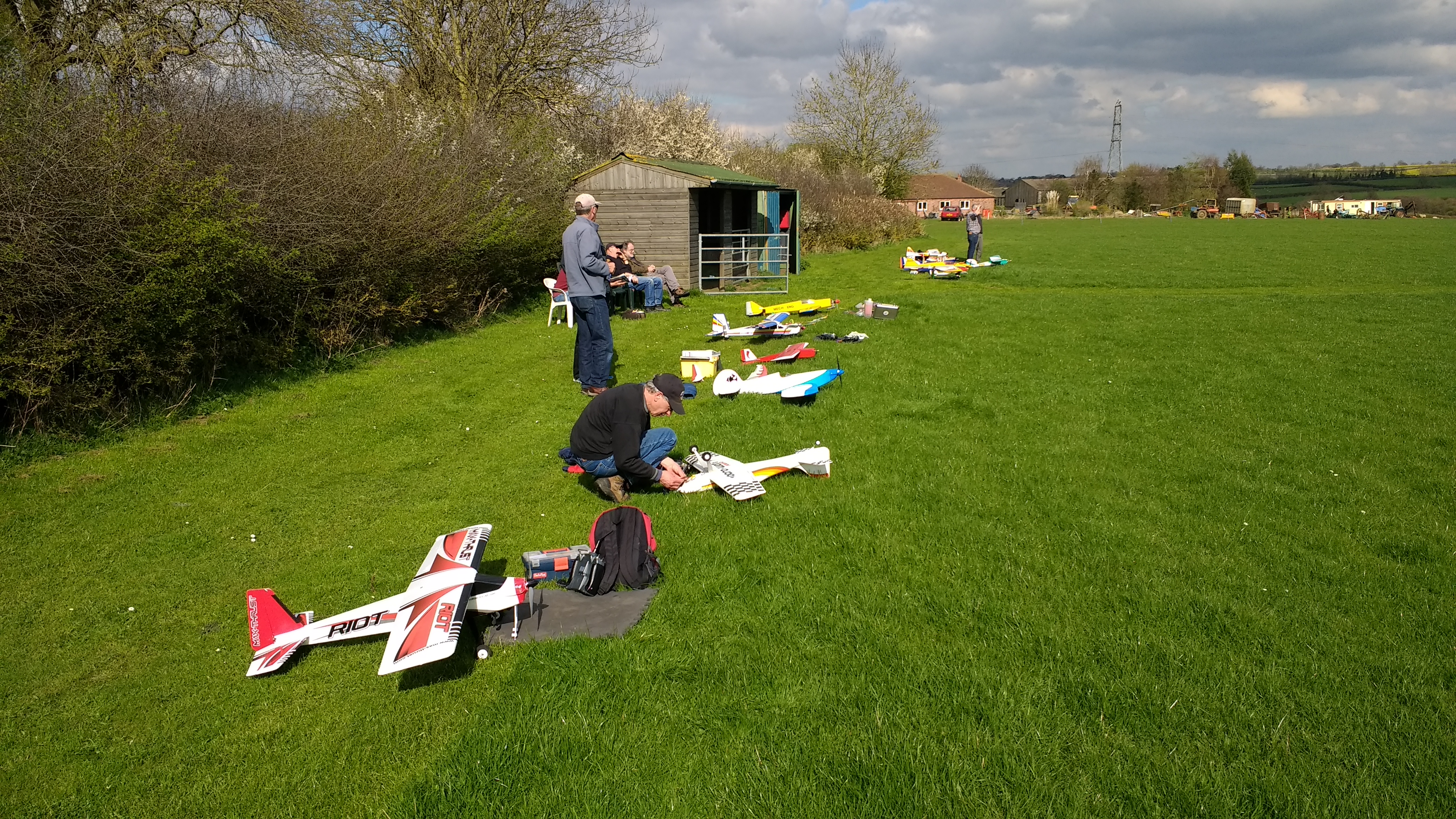
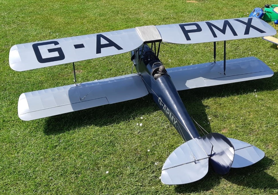
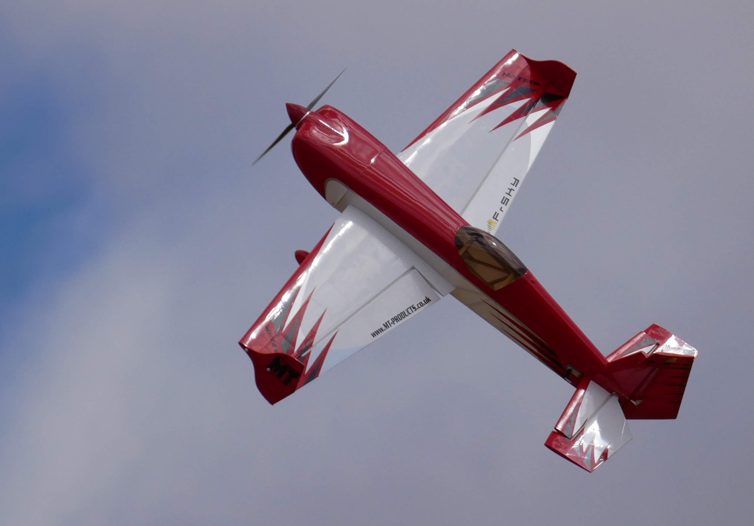
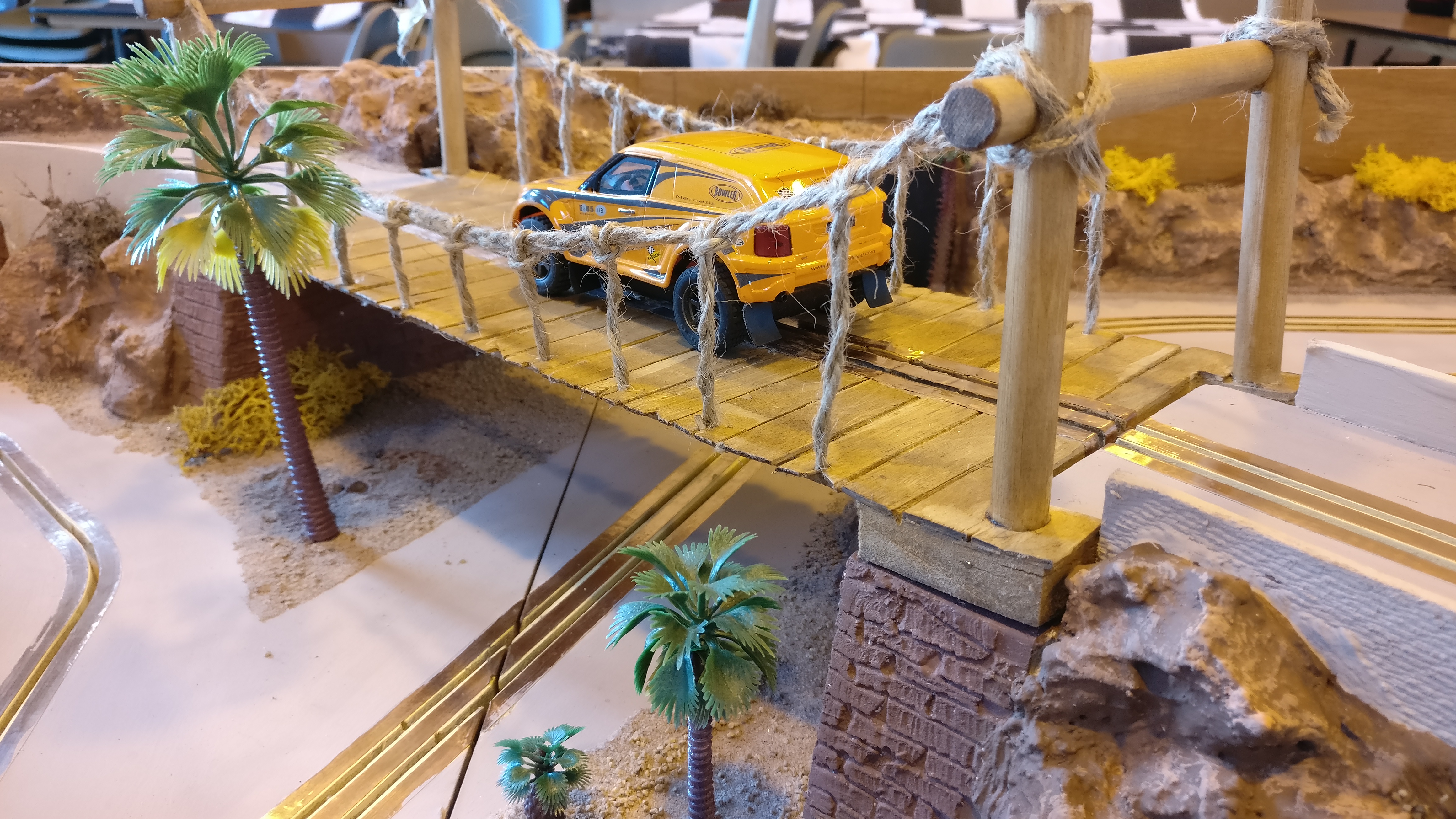
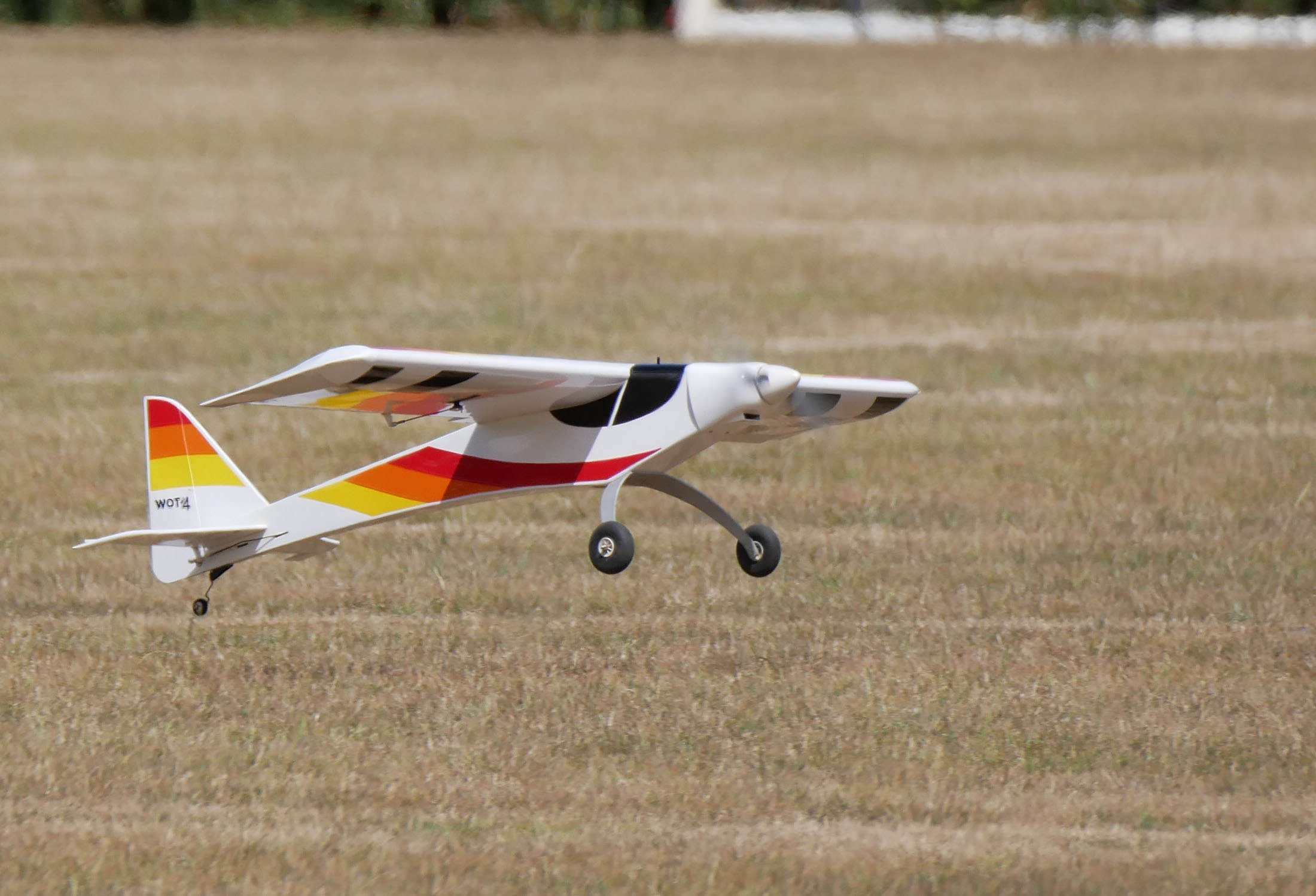
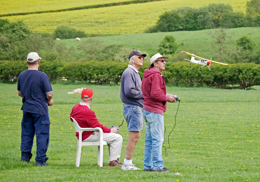
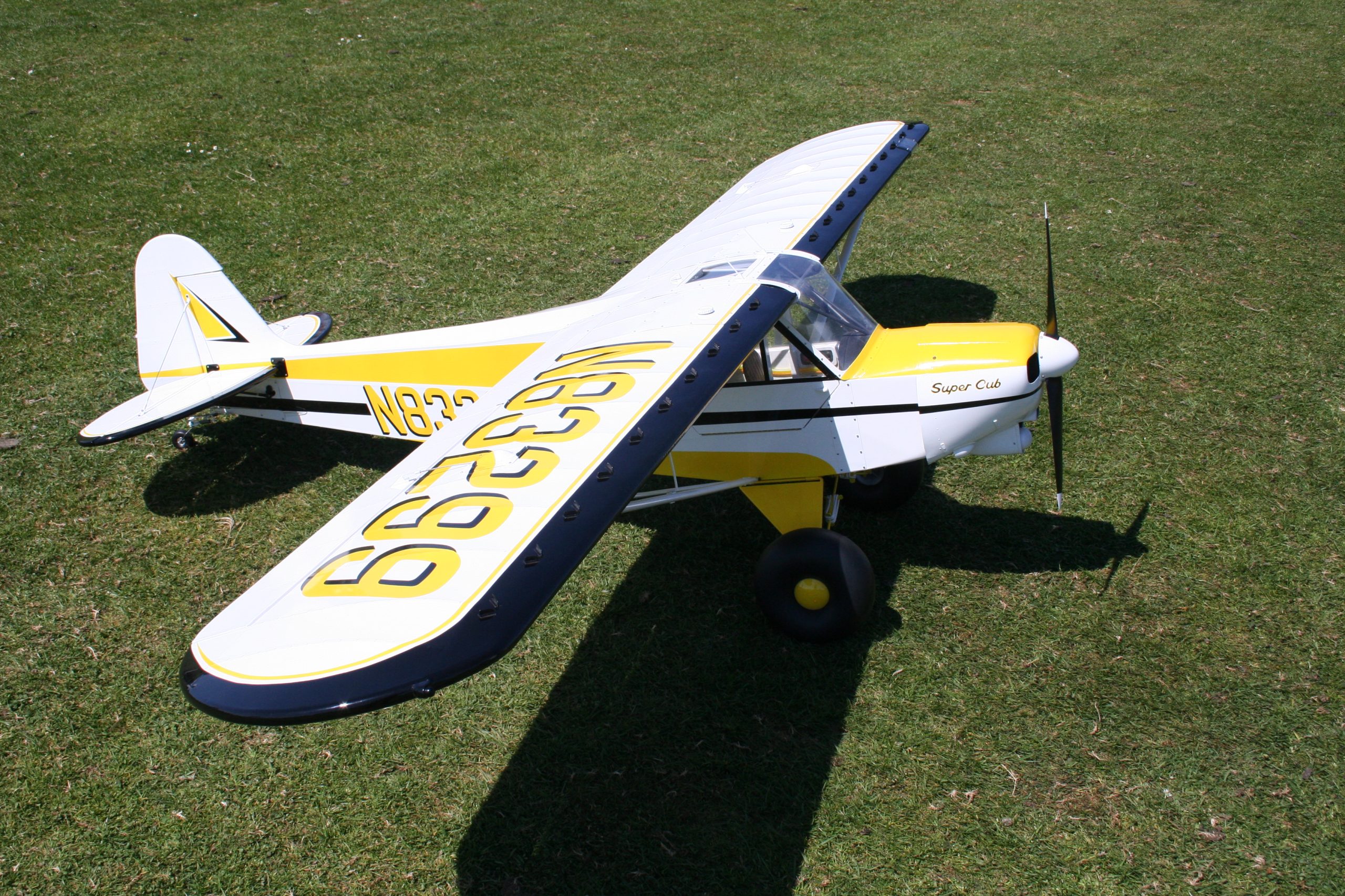
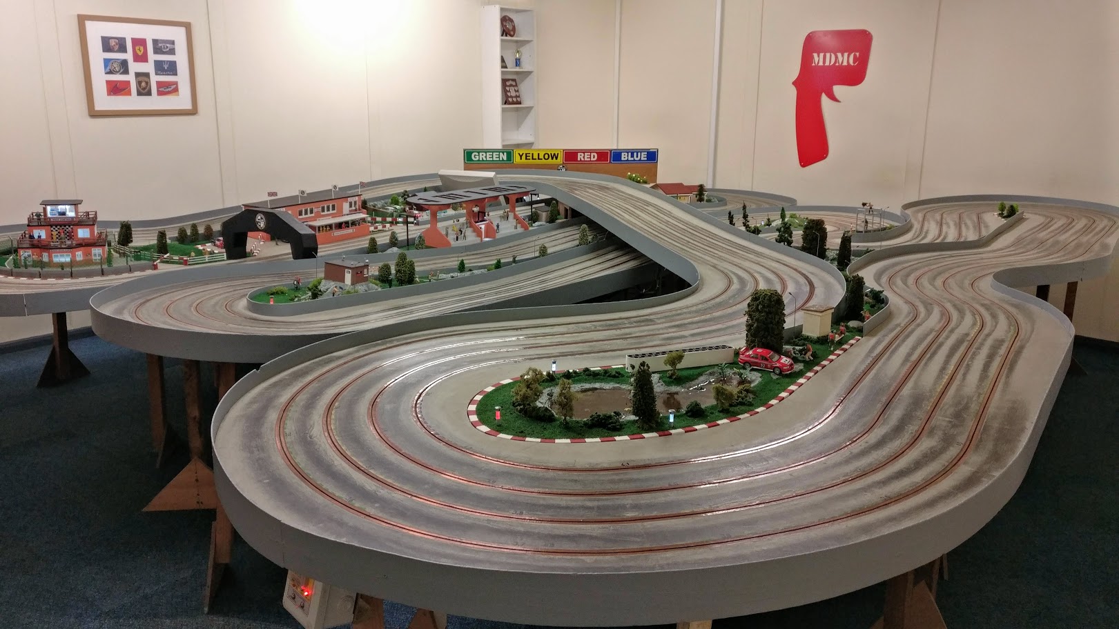
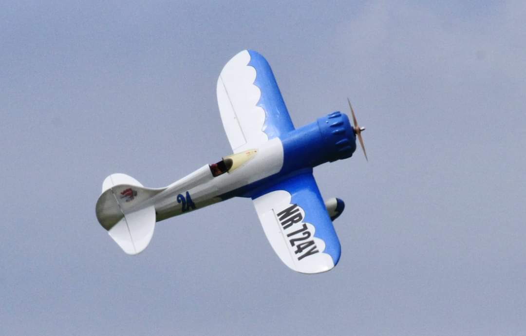
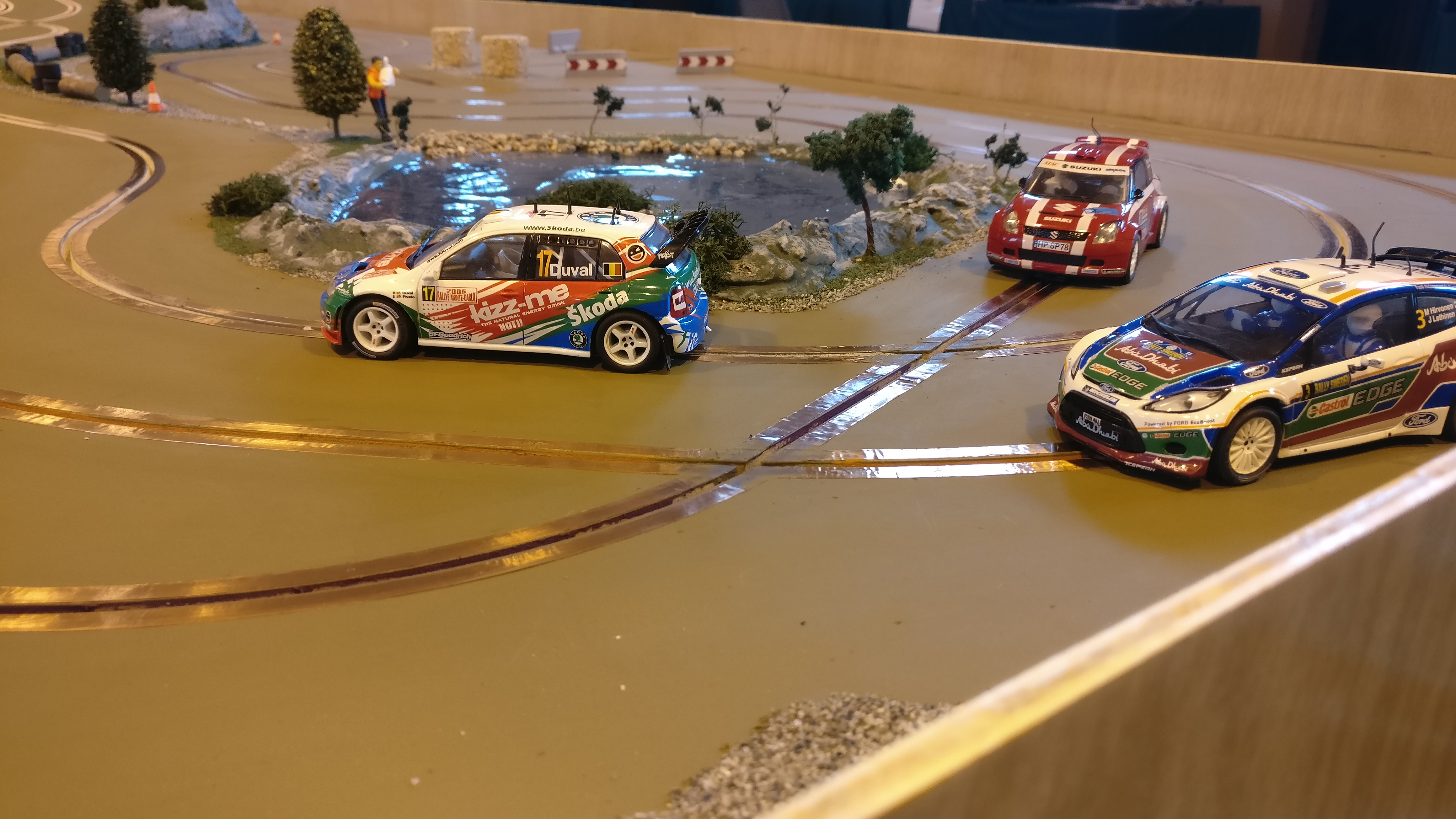
The Club supports a wide range of modelling activities and associated interests.
This website is designed to provide a source of information for existing members and for those who may wish to join the Club.
The Club encourages members to provide content to their website to keep it up to date.
Please send the Club with any information you think may be of interest to others on the following page: Contact Us Thank you!
Pay your Club fees and BMFA membership on-line – see the ‘Joining the Club‘ section for more details.